Digital vs Electronic Relays: Which Offers Better Selective Protection?
Selective protection depends on accurate timing and logic. Digital relays offer precise settings and communication. Electronic relays provide simple, isolated hardware. The right choice depends on your system complexity, network needs, and maintenance preference.
- Digital relays use microprocessors to handle complex logic and communication, supporting precise selective tripping in large networks.
- Electronic relays rely on analog or solid-state hardware, offering simpler operation and easier physical isolation from digital noise.
- The best choice depends on your system size, the need for data communication, and how critical precise timing is for your protection scheme.
- Consider maintenance access, spare parts availability, and the skill level of your operations team when selecting relay technology.
What is the core difference between digital and electronic relays?
The distinction comes down to how the relay processes electrical signals to make a trip decision. Digital relays use a microprocessor to sample voltage and current, apply software-based logic, and calculate trip times with high precision. Electronic relays use analog circuits or solid-state components to compare incoming signals against mechanical or electronic thresholds. Both types perform the same fundamental job: detect a fault and open a circuit breaker to protect equipment.
The core architecture drives the performance. A digital relay converts the analog primary current into a digital signal, often via a Current Transformer (CT) or instrument transformer, and feeds it into an A/D converter. The microprocessor then executes protection algorithms that can include inverse time curves, distance relays, or differential logic. An electronic relay, by contrast, routes the signal through op-amps, comparators, and timing circuits. These circuits compare the instantaneous current against a set reference. When the signal exceeds the reference, the timing circuit initiates a trip pulse.
The choice between them is not about one technology being superior. It is about which technology fits your specific protection requirements. Selective protection requires that the correct breaker opens for a given fault, without tripping upstream or parallel equipment. This demand for precision is where the differences between the two technologies become most apparent. In a radial distribution system, a fault at the end of a feeder must trip the closest breaker before the substation feeder breaker sees the fault current. If the timing is off by a few milliseconds, the wrong breaker may operate, or the system may trip multiple breakers in a cascade.
How do digital relays handle selective tripping?
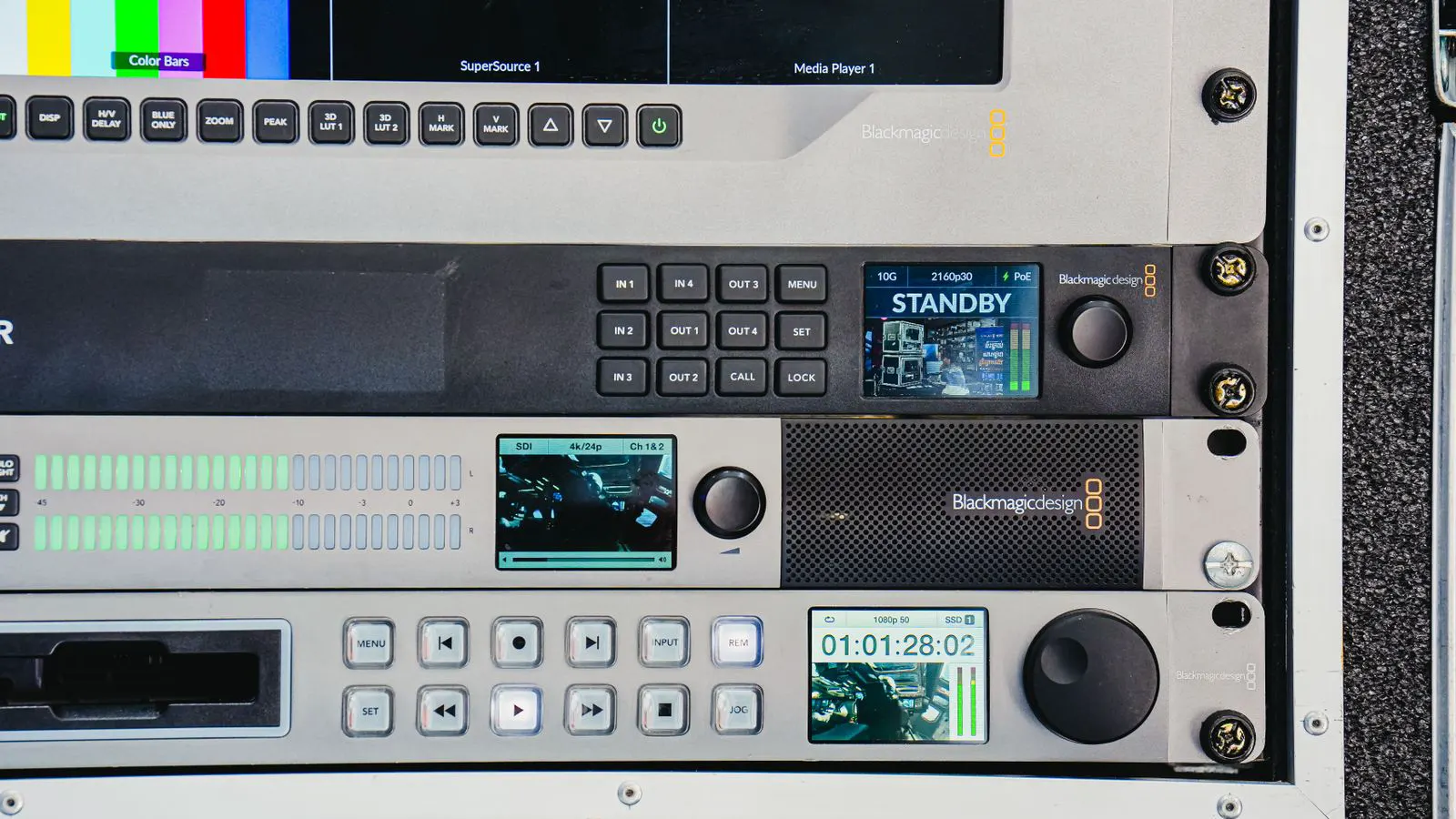
Digital relays sample primary currents at high rates and process the data in software. This allows them to implement complex protection schemes, such as distance protection, differential protection, and time delay coordination, with high accuracy. The software can be updated or reconfigured to match changes in the network without replacing hardware.
For selective tripping, this precision is a major advantage. In a radial system, a digital relay can calculate the exact impedance distance to a fault and trip within a set time. For example, a Zone 1 distance relay might operate in 40 milliseconds. A Zone 2 relay might operate in 150 milliseconds. The digital processor calculates the voltage and current phasors at each cycle of the AC waveform. It compares the measured impedance to the pre-set blocking zones. This calculation happens thousands of times per second, allowing the relay to distinguish between a fault at the end of a feeder and a fault at the busbar.
In a meshed network, digital relays can coordinate with other relays using communication protocols to ensure the closest breaker operates first. This is often done using directional protection or pilot tripping. If Relay A detects a fault, it can send a pilot signal to Relay B, instructing it to trip. This removes the need for long time delays and allows for faster, more selective clearing of faults. The ability to adjust settings and logic remotely also supports faster commissioning and troubleshooting. Engineers can connect a laptop to the relay via Ethernet or serial port to upload new settings or download event logs.
However, digital relays are sensitive to electromagnetic interference and require stable power. If the microprocessor resets or the communication link fails, the relay may default to a basic function or fail to trip. This makes power quality and grounding critical for reliable operation. A noisy environment can corrupt the A/D converter input, leading to false trips or a failure to trip. Proper shielding of the relay cabinet and filtering of the control power supply are standard mitigation practices.
How do electronic relays support selective protection?
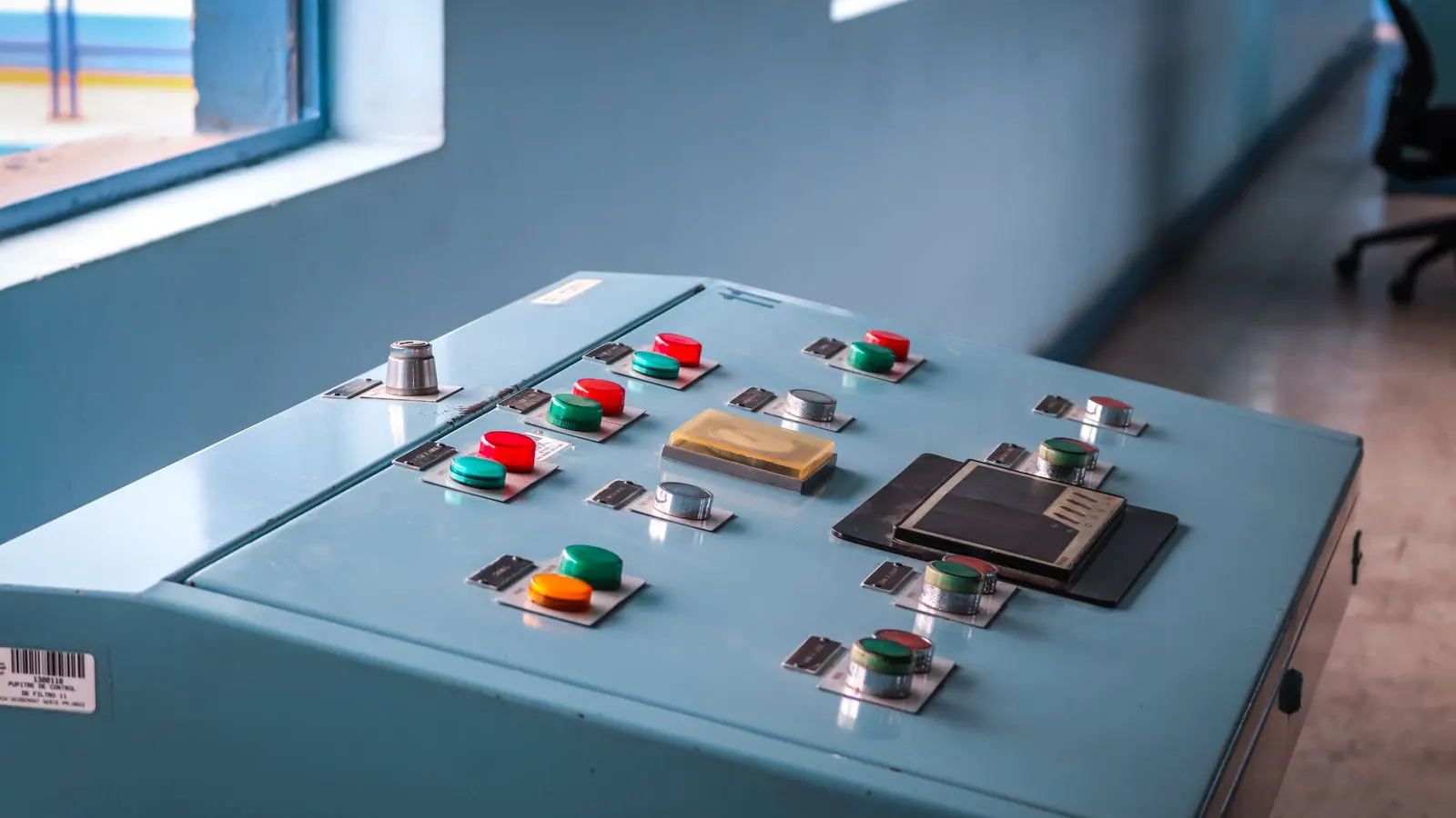
Electronic relays use analog or solid-state circuits to compare current or voltage signals against a set threshold. They are often simpler in design and do not rely on a central processor for core protection functions. This simplicity can be an advantage in harsh environments where digital noise might interfere with operation.
For selective tripping, electronic relays typically use time-delay circuits to coordinate with other breakers. While they can achieve the required coordination times, the precision is generally lower than that of digital relays. This makes them well suited for simpler systems, such as distribution feeders or small substations, where complex logic is not required.
An electronic overcurrent relay, for instance, might use a thermal-magnetic trip mechanism. The magnetic part operates instantly on high current, while the thermal part uses a bimetallic strip or a solid-state thermal simulator to provide inverse time characteristics. The time delay is set by adjusting a mechanical dial or a potentiometer. This physical adjustment is straightforward but less precise than software configuration. For a simple two-tier coordination, where a feeder breaker protects a motor, an electronic relay is often sufficient. The feeder relay trips in 1.5 seconds, and the motor protection device trips in 0.1 seconds. The difference is large enough that precision is less critical.
The main limitation is flexibility. Changing the protection logic or settings usually involves physical adjustments, such as replacing a resistor or a time base component. This means the process is slower and may require on-site access to the relay. If you need to change the inverse time curve from a standard curve to a custom curve, an electronic relay may not support it at all, requiring a physical swap of the relay.
Comparison of relay technologies for protective schemes
The table below summarizes the key characteristics of each technology. This helps you match the relay type to your specific requirements.
| Option | Best for | Limitations |
|---|---|---|
| Digital Relay | Large networks, complex coordination, remote monitoring, and precise timing | Sensitive to noise, requires stable power, and may need specialized software for updates |
| Electronic Relay | Simple systems, harsh environments, and sites with limited communication infrastructure | Less flexible, slower to reconfigure, and generally lower precision in timing |
| Hybrid Relay | Systems that need digital features but with a solid-state protection core | Higher cost, and the complexity of both systems can increase maintenance needs |
Hybrid relays combine the precision of digital processing with the robustness of electronic protection circuits. They are often used in medium-voltage substations where reliability and adaptability are both needed. In a hybrid design, the primary protection function, such as overcurrent tripping, might be handled by a solid-state circuit that operates independently of the microprocessor. The microprocessor handles data logging, communication, and secondary functions. This architecture ensures that the relay can trip even if the digital part fails, provided the power supply is healthy.
However, they are more expensive and may require a higher level of technical skill to maintain. The maintenance team must understand both the analog and digital components. A failure in the power supply regulation might affect both parts, requiring a thorough diagnostic process.
When should you choose a digital relay?
Choose a digital relay if your protection scheme requires precise timing, complex logic, or integration with a supervisory control and data acquisition system. This is typical for high-voltage transmission, large industrial plants, and substations with multiple feeders and interconnections. The ability to store data, log faults, and communicate with a central system adds significant value for operations and maintenance teams.
Consider a substation with ten feeders. If a fault occurs on Feeder 5, a digital relay at the substation can log the exact fault current, the trip time, and the voltage collapse. This data is uploaded to the SCADA system. The operations team can see the event in real-time and investigate the root cause. This level of visibility is not available with a basic electronic relay.
The setting process for digital relays is more involved. Engineers must configure the software, upload the settings, and verify that the logic matches the single-line diagram. A common mistake is to assume that the default settings are correct. They are not. Every digital relay must be tailored to the specific fault levels and network topology. The engineer must calculate the minimum fault current at the relay location and set the pickup current slightly below that value. They must also calculate the maximum load current and set the inverse time curve so that the load does not cause a nuisance trip.
If you have a skilled team and the infrastructure to support data communication, a digital relay is the better fit. The long-term benefits in flexibility and data access usually justify the higher initial cost. The ability to perform self-tests and monitor the health of the relay components adds another layer of reliability.
When should you choose an electronic relay?
Choose an electronic relay if your system is simple, located in a harsh environment, or has limited access to communication infrastructure. Electronic relays are common in rural substations, small distribution networks, and sites where the primary concern is reliable operation over complex features.
Imagine a remote substation in a mining area. The environment is dusty, and the power supply is unstable. A digital relay might be susceptible to dust buildup on the PCB and voltage spikes that could reset the processor. An electronic relay, with its simpler circuitry and robust components, is less likely to fail in these conditions. The setting process is more physical. An engineer must adjust the time base or the pickup current using a screwdriver or a handheld tester. This can be a disadvantage if the relay is in a hard-to-reach location. However, the lack of complex software means that the relay is less likely to suffer from configuration errors.
For a small number of feeders with straightforward coordination, an electronic relay can be a cost-effective and reliable solution. It does not require a computer connection or a stable power supply as sensitive as a digital relay. The maintenance team can troubleshoot issues by checking voltages and continuity with a multimeter, rather than needing specialized software.
How to verify selective tripping before commissioning
Regardless of the relay type, selective tripping must be verified before the system is energized. This involves checking that each relay is set to the correct time and that the coordination sequence is correct. A common approach is to use a relay test set to simulate a fault and measure the actual trip time of each breaker in the sequence.
The test must account for the breaker operating time, which varies with the load and the breaker design. The relay trip time plus the breaker operating time must be less than the next upstream relay trip time plus its breaker operating time. This margin is often called the selectivity margin.
For example, consider two breakers: Breaker A (upstream) and Breaker B (downstream). Breaker B is set to trip in 100 ms, and its breaker operates in 30 ms. The total time for Breaker B to clear the fault is 130 ms. Breaker A is set to trip in 300 ms, and its breaker operates in 30 ms. The total time for Breaker A is 330 ms. The margin is 200 ms, which is sufficient. If Breaker A were set to trip in 120 ms, the total time would be 150 ms. The margin would be 20 ms, which is too small and would likely cause both breakers to trip.
If the margin is too small, the scheme will not be selective. This can cause multiple breakers to trip, leading to a larger outage than necessary. The test results should be documented and stored in the relay setting records. This document is referenced during any future changes to the protection scheme. The test set must be calibrated to ensure accuracy. A drift in the test set output can lead to incorrect trip time measurements.
Final considerations for your selection
The choice between digital and electronic relays is a trade-off between precision and simplicity. Digital relays offer more features and better data access, but they require more support infrastructure. Electronic relays are simpler and more robust, but they offer less flexibility.
Consider the size of your network, the complexity of the coordination, and the skill level of your maintenance team. A large, interconnected system will likely benefit from digital relays. A small, isolated substation may be better served by electronic relays. There is no single answer. The best choice is the one that matches your specific protection requirements and operational context.
When selecting a relay, start with the protection scheme. Draw the single-line diagram and identify all fault paths. Calculate the fault current at each point. Determine the required trip times for each breaker. Then, select the relay technology that can meet those requirements within budget and maintenance constraints. Document the decision process. This documentation will be valuable if the network changes in the future or if a fault occurs and the decision needs to be reviewed.
Frequently asked questions
What is the main difference in trip time accuracy between digital and electronic relays?
Digital relays offer higher precision in trip time calculation due to software-based processing. Electronic relays rely on analog or solid-state timing circuits, which may have slightly lower accuracy.
Can electronic relays be upgraded to digital functionality?
Generally no. The core hardware is different. Upgrading would require replacing the relay with a digital model. This is a significant capital expense.
How does electromagnetic interference affect digital relays?
Digital relays are more sensitive to electromagnetic interference than electronic relays. Proper grounding and shielded cables are required to prevent false trips or missed trips.
What is the typical maintenance difference between the two types?
Digital relays require periodic software checks and firmware updates. Electronic relays require physical adjustments and component replacement. Both require regular testing, but the nature of the work differs.
Which type is more common in modern high-voltage substations?
Digital relays are more common in modern high-voltage substations due to the need for precise coordination, remote monitoring, and data logging.