Relay Setting Checklist: Verify Trip Times Before Commissioning
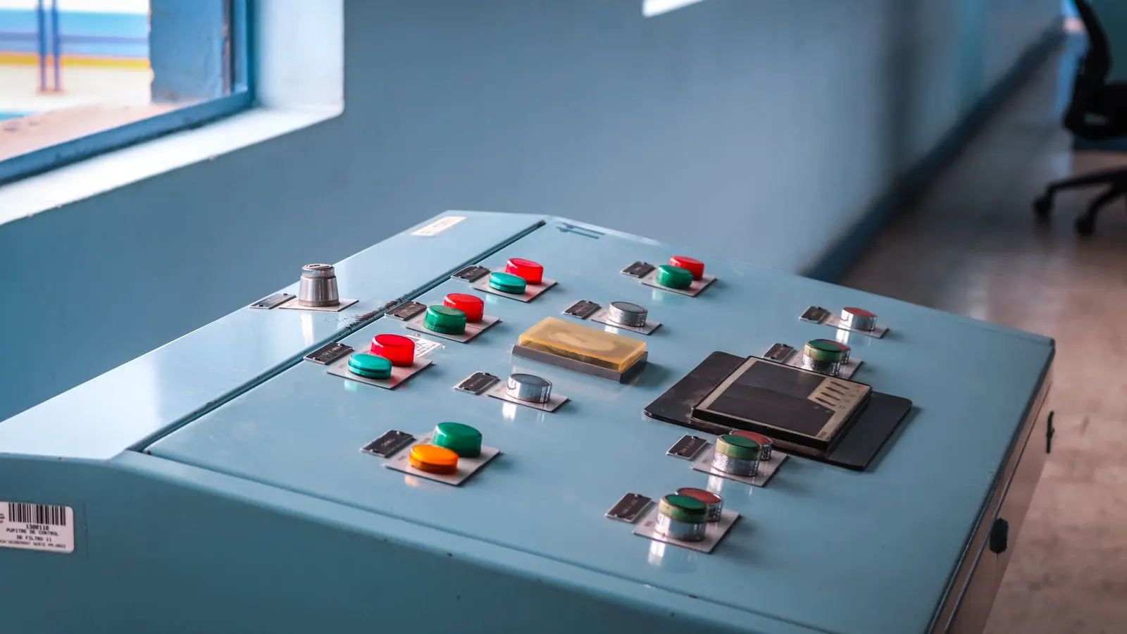
A relay setting checklist confirms that all protection parameters are configured correctly before energization. This guide outlines verification steps for trip times, communication, and coordination to prevent commissioning errors and system failures.
- Verify relay trip times against the one-line diagram and coordination study before commissioning.
- Check communication paths between relays, protective devices, and control systems to ensure data integrity.
- Test all relay outputs and inputs to confirm proper operation of circuit breakers and alarms.
- Review documentation and maintain a complete audit trail for regulatory compliance and future maintenance.
Commissioning switchgear is a high-risk phase where small configuration errors become operational hazards. A complete relay setting checklist ensures that every parameter is verified before the system goes live. This document provides a structured audit of protection relay settings, focusing on trip times, communication, and coordination. Use this guide during pre-startup testing to identify misconfigurations before they cause protection failures or equipment damage.
Verify Relay Trip Times Against Coordination Study
The first step in any relay setting checklist is to confirm that trip times match the coordination study. Pull the approved coordination curve and compare it with the relay’s configured settings. A mismatch here can cause a downstream breaker to trip before an upstream relay, leading to unnecessary shutdowns or loss of selectivity.
Check each relay’s setpoint for overcurrent, overvoltage, undervoltage, and ground fault. Record the configured values in your commissioning report. If the relay has multiple trip levels, verify that each level triggers at the expected threshold. Use a relay simulator or injection unit to test the actual trip time. Compare the measured time with the calculated time in the coordination study.
Red flags:
- Measured trip time exceeds the calculated value by more than a few milliseconds.
- The coordination study is outdated and does not reflect recent changes to the electrical system.
- Relay settings are set to the factory defaults rather than project-specific values.
Confirm Relay Communication Paths
Modern protective relays rely on digital communication for settings, data transfer, and coordination. A relay setting checklist must include verification of all communication interfaces. Confirm that the relay’s IP address, subnet mask, and gateway are configured correctly. Test the connection to the SCADA system, historian, or local control panel.
Check the communication protocol. Verify that the relay and the control system use the same version of the protocol. For example, if the relay uses IEC 61850-9 and the control system expects IEC 61850-4, the data will not be parsed correctly. Test the integrity of the communication link by transmitting a known value from the relay to the control system. Compare the received value with the transmitted value.
Red flags:
- Intermittent communication drops during testing.
- The control system displays incorrect or stale data from the relay.
- Firewall or network segmentation blocks the required communication ports.
Test Relay Inputs and Outputs
The physical connections between the relay and the switchgear must be verified. A relay setting checklist includes testing all inputs, such as current transformers, voltage transformers, and auxiliary contacts. Confirm that the CT ratio matches the relay’s configured ratio. A mismatch here will cause the relay to misjudge the fault current.
Test the relay’s outputs, including trip contacts, alarm relays, and communication outputs. Verify that the trip output closes the circuit when the relay is triggered. Check the contact rating to ensure it matches the load. For example, if the trip contact drives a 24 VDC coil with a 100 mA draw, the contact must be rated for at least that current.
Red flags:
- The CT ratio does not match the relay’s configuration.
- The trip contact fails to close under load.
- Auxiliary contacts are wired in series instead of parallel, causing a single point of failure.
Review Relay Configuration and Documentation
The relay’s internal configuration must be documented and version-controlled. A relay setting checklist requires confirmation that the correct configuration file is loaded. Compare the loaded configuration with the approved design document. Any deviation must be explained and approved by the project manager.
Check the relay’s firmware version. Ensure it is compatible with the control system and that all known bugs are addressed. Review the relay’s event log. If the log contains errors from the factory test phase, investigate and clear them before commissioning.
Red flags:
- The loaded configuration does not match the design document.
- The firmware version is older than the version tested during factory acceptance.
- The event log contains unresolved errors or warnings.
Perform End-to-End System Testing
Individual relay tests are necessary but not sufficient. A relay setting checklist must include an end-to-end system test. Energize the system and inject a fault current using a relay simulator. Verify that the relay triggers, the trip output closes, the circuit breaker opens, and the alarm sounds. Time the entire sequence from fault initiation to breaker opening.
Compare the measured system response time with the calculated response time. If the measured time is longer than expected, investigate the cause. It may be due to a slow relay, a long trip contact closing time, or a mechanical issue with the circuit breaker.
Red flags:
- The circuit breaker fails to open after the relay trip.
- The alarm does not sound or is delayed.
- The system response time exceeds the calculated value by more than the allowed tolerance.
Maintain the Commissioning Audit Trail
A complete relay setting checklist is only useful if it is documented. Record every test result, deviation, and correction. Attach the relay configuration file, the coordination study, and the test reports to the commissioning file. This audit trail is required for regulatory compliance and for future maintenance.
If a deviation is found, document the cause, the corrective action, and the verification of the fix. For example, if a CT ratio was incorrect, record the original value, the corrected value, and the test that confirmed the fix.
Red flags:
- Missing test reports or unsigned commissioning forms.
- Deviations are not documented or are corrected without approval.
- The relay configuration file is not archived with the commissioning record.
Quick Reference Table for Relay Setting Verification
The table below provides a quick reference for the key items in a relay setting checklist. Use this table during pre-startup testing to ensure no item is missed.
| Item | Verification Method | Typical Red Flag |
|---|---|---|
| Trip Time | Measure with relay simulator | Exceeds calculated time |
| CT Ratio | Compare with relay config | Mismatch between CT and relay |
| Communication | Transmit known value to SCADA | Data corruption or loss |
| Trip Output | Close circuit under load | Contact fails to close |
| Firmware Version | Check relay display | Older than tested version |
Final Checks Before Energization
Before switching on the main breaker, perform a final walk-through of the relay setting checklist. Confirm that all relays are powered up and communicating. Verify that all trip outputs are in the “ready” state. Check that the system alarms are clear.
If any item in the checklist is not verified, do not energize the system. Resolve the issue first. A complete relay setting checklist is your last line of defense against commissioning errors.
Frequently asked questions
How often should a relay setting checklist be performed?
Perform the checklist during initial commissioning and after any major modification to the protection system. Annual verification is recommended for critical systems.
What is the most common error found during relay commissioning?
The most common error is a mismatch between the CT ratio and the relay configuration. This causes the relay to misjudge the fault current.
Can a relay setting checklist be automated?
Partial automation is possible using relay testing software. However, physical verification of inputs and outputs must still be performed manually.
What should be done if a relay fails a test?
Isolate the relay and investigate the cause. If the relay is faulty, replace it. If the issue is a configuration error, correct the setting and re-test.
Does a relay setting checklist apply to all types of relays?
Yes, the principles apply to all protective relays. However, specific test methods may vary depending on the relay type and application.