How to Install MV Busbar Systems: Step-by-Step
Installing an MV busbar system requires strict alignment, proper torque, and verified insulation. This guide outlines prerequisites and steps to connect busbars safely, preventing thermal damage, loose connections, and commissioning failures during switchgear installation.
- Verify the installation environment and verify the busbar configuration before cutting or bolting.
- Use calibrated torque tools and record every fastening torque to prevent future thermal failures.
- Maintain strict clearance and insulation checks before energization to protect personnel and equipment.
- Perform a final commissioning test that confirms continuity, insulation resistance, and proper busbar movement.
Before You Start: Prerequisites and Site Readiness
An MV busbar system installation begins long before the first bolt is tightened. The site must be prepared, the design package confirmed, and the installation team aligned on the mechanical and electrical sequence. Skipping these prerequisites leads to rework, misaligned busbars, and commissioning delays.
The installation area requires a clean, dry, and well-lit workspace. Dust on busbar surfaces or inside switchgear enclosures degrades insulation and affects contact resistance. Confirm that the floor or mounting platform can support the weight of the busbar assembly. Heavy busbars, especially copper or aluminum sections with heavy busbar supports, require adequate lifting capacity and rigging points.
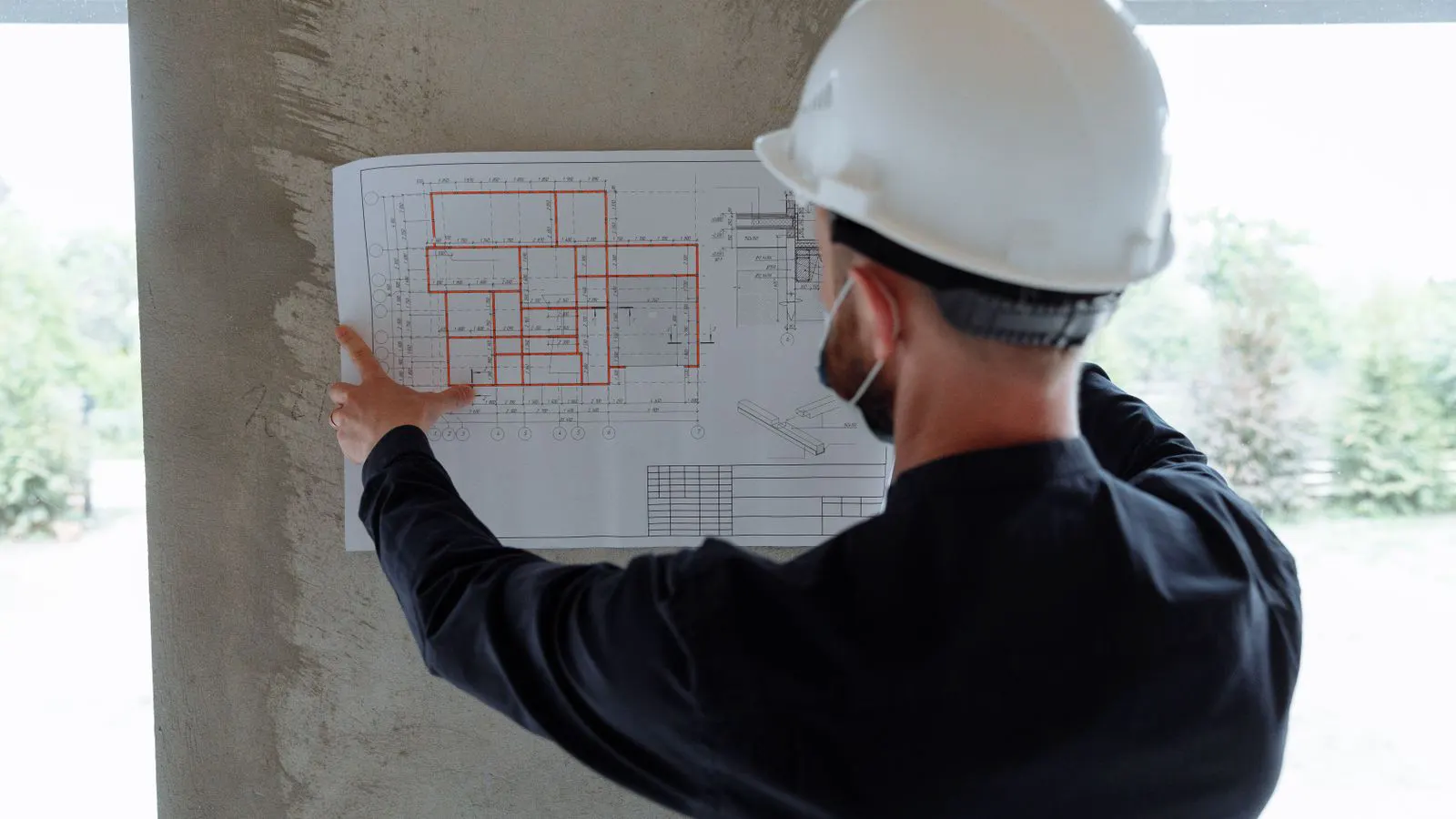
Review the factory drawings and the as-built configuration. Each MV busbar system has a specific layout. The number of busbar sections, the type of busbar (strip, tube, or hollow), and the connection points to switchgear compartments must match the site plan. Verify that all busbar supports, clamps, and insulating materials are present. A missing clamp or a wrong insulator thickness will force field modifications that compromise the design.
Gather the required tools. You will need calibrated torque wrenches for every fastener, a digital multimeter, an insulation resistance tester, a busbar alignment gauge or laser level, and a torque recording log. The torque values come from the manufacturer’s installation manual. Do not estimate torque. A loose busbar connection creates a hot spot that can ignite insulation and damage the busbar.
Confirm the personnel qualifications. The installation team must be competent in high-voltage safety, lockout/tagout procedures, and electrical testing. The site must have a defined exclusion zone before any energization or high-voltage testing.
Step 1: Unpack and Inspect the Busbar Components
Remove the busbar sections from their packaging carefully. Inspect each section for physical damage. Look for bent edges, crushed tube busbars, or damaged insulation. Check the contact surfaces. They must be clean, free of oxidation, and free of scratches. Even a small scratch on a contact face increases resistance and creates heat during load operation.
Verify the part numbers against the packing list. Each busbar section, insulator, support, and connector should match the design. If a component is damaged or incorrect, tag it and quarantine it. Do not install a damaged busbar. The risk of insulation failure or mechanical failure is too high.
Step 2: Position and Align the Busbar Sections
Lift the busbar sections into position using the approved method. Use lifting slings that do not damage the insulation or the busbar surface. Place the busbars on the designated supports. The supports must be correctly positioned. A misaligned support causes the busbar to bear uneven mechanical stress.
Use an alignment gauge or laser level to check the alignment of the busbar sections. The busbars must be straight and level. Misalignment creates bending stress on the busbar and puts extra load on the insulators. The allowable deviation is defined by the manufacturer. Typically, the deviation is small, often in the range of a few millimeters over a long run.
Check the clearance between the busbars and the enclosure walls, other busbars, and grounding. The clearance must meet the design requirements. If the clearance is insufficient, the insulation may be damaged during installation or operation. Adjust the supports before moving to the next step.
Step 3: Connect the Busbar Sections
Connect the busbar sections in the sequence defined by the design. This is usually end-to-end connections. Clean the contact surfaces again if any dust or debris has settled. Apply the contact compound if specified by the manufacturer. Some busbar connections require a specific contact paste to reduce resistance.
Insert the connecting pins or lugs. Align the holes carefully. Force is not acceptable. If the holes do not align, stop and check the alignment of the busbars. Forcing a connection creates a stress concentration that can crack the busbar or the insulator.
Tighten the fasteners in a cross-pattern. Start with a light tightening to seat the parts. Then tighten to the specified torque value. Use a calibrated torque wrench. Record each torque value in the installation log. The torque value ensures the contact resistance remains low and the mechanical joint stays secure.
Step 4: Insulate and Protect the Busbars
After the busbars are connected, inspect the insulation. Check that all insulating materials are in place. Look for gaps between the busbar and the ground. Apply insulation tape or protective covers where specified. The busbar must be fully insulated from the enclosure and from other conductive parts.
If the busbar is exposed, install protective covers or guards. These protect the busbar from accidental contact and from debris. The covers must not interfere with the thermal expansion of the busbar. Some busbar systems use sliding joints or expansion joints to allow for thermal movement. Ensure these joints are correctly installed.
Step 5: Perform Electrical Testing
With the busbar system connected, perform electrical testing. The busbars must be de-energized for these tests. Use a digital multimeter to check continuity. Measure the resistance between the busbar sections. The reading should be very low, indicating a good connection. If the resistance is high, there is a loose connection or a damaged contact. Re-torque the fastener and re-test.
Use an insulation resistance tester to measure the insulation resistance between the busbar and ground. The test voltage is defined by the system voltage. The measured resistance must exceed the minimum value specified by the applicable standard. A low insulation resistance indicates moisture, contamination, or damage. Dry or clean the insulation before proceeding.
Check the phase-to-phase insulation if the design requires it. The busbars must be insulated from each other. A short between phases can cause a fault during commissioning.
Step 6: Commission the Switchgear and Busbar System
Connect the busbar system to the switchgear compartments. Verify that the busbar connections match the switchgear terminals. The busbar must connect to the correct phase. A phase swap can cause a short circuit or damage to the equipment.
Set the switchgear in the test position. Perform a low-voltage control test. Check that the switchgear operating mechanisms respond correctly to the control signals. Verify that the indicators show the correct status.
Energize the busbar system at the test voltage. Monitor the busbar during energization. Listen for any abnormal sounds. Check for any signs of overheating. Use an infrared thermometer if available to check the contact points. A temperature rise above the normal range indicates a loose connection or a high-resistance point.
Common Mistakes in MV Busbar Installation
One common mistake is skipping the alignment check. Installers often assume the busbars are straight because they look straight. A small misalignment can cause a long-term failure. Always use a gauge or laser level.
Another mistake is using the wrong torque. Some installers use a torque wrench without calibrating it. An uncalibrated wrench gives an inaccurate torque value. A loose connection creates heat. A tight connection can crack the insulator. Always calibrate the torque wrench before use.
A third mistake is ignoring the contact compound. Some busbar connections require a specific compound to reduce resistance. Skipping this step increases the contact resistance and creates a hot spot.
A fourth mistake is not recording the torque values. Without a record, it is impossible to verify the installation later. A future maintenance team will not know if the busbar was torqued correctly. Always record the torque values in the as-built documentation.
Final Verification
The final verification step confirms that the MV busbar system is ready for service. Review the installation log. Every torque value must be recorded. Every test must be passed. The alignment must be within the specified limits.
Perform a visual inspection. Check for any loose fasteners, damaged insulation, or missing covers. Check for any signs of overheating from the energization test. If any defect is found, correct it before commissioning.
Obtain sign-off from the responsible engineer. The commissioning report must be completed. The busbar system is now ready for normal operation.
Frequently asked questions
What is the typical torque range for MV busbar fasteners?
The torque range depends on the fastener size, the busbar material, and the manufacturer specification. Always use the torque value from the installation manual.
Can I use any torque wrench for MV busbar installation?
No. Use a calibrated torque wrench that matches the required torque range. An uncalibrated wrench can give an inaccurate value and cause a loose or damaged connection.
How do I check if the busbar alignment is correct?
Use an alignment gauge or a laser level. Check the straightness and level of the busbar against the manufacturer's allowable deviation.
What should I do if the insulation resistance test fails?
Stop the commissioning. Identify the cause. It is usually moisture, contamination, or damage. Clean or dry the insulation, then re-test.
Do I need to apply contact compound to busbar connections?
It depends on the design. Some busbar connections require a contact compound to reduce resistance. Check the manufacturer's installation manual.